11.4.3 Images
As you may recall from your study of computer graphics in Chapter 6, digital images are composed of a large number of basic picture elements called pixels. Each pixel represents the particular brightness and color value of a tiny dot that is to be displayed on a screen or drawn on paper. By arranging pixels into two-dimensional grids, an image can be formed.
Digital images are most often represented within the computer as bit maps. A bit map is a two-dimensional array of values, where each value corresponds directly to a pixel’s intensity or color. The simplest digital images are monochrome (black and white) images that use one bit per pixel, “1” for black and “0” for white, or vice versa. Images that incorporate multiple colors or shades of gray require multiple bits per pixel. For example, an image that uses four shades of gray (black, dark gray, light gray, white) would require two bits per pixel. These bit values might map to the pixel “color” as “00” for black, “01” for dark gray, “10” for light gray, and “11” for white. Full color digital images (capable of displaying millions of colors) require twenty-four or more bits per pixel.
Figure 11.23 presents a digital image and the bit map that underlies it. The image is very simple, containing the word “Hi” drawn as black letters on a white background. The “resolution” of the image is eleven pixels per line by nine lines. Each pixel represents one of only two colors, “1” is used for black and “0” for white. In order to help clarify the meaning of the bit map, the pixel grid lines are shown in the figure. In reality, these lines would not be displayed. They simply mark the boundaries of each pixel.
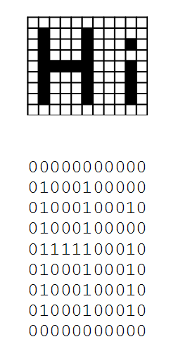
Figure 11.23: A monochrome image and its underlying bit map.
Although we presented the bit map in Figure 11.23 in its two-dimensional form, as we have seen, computer memory is really a one-dimensional structure. So, the bit map would actually be stored in a form similar to the following:
0000000000001000100000010001000100100010000001111100010010001000100100010001001000100010 00000000000
As long as we know where the image begins and the dimensions of the image (the number of pixels per line and the number of lines per image) we will be able to reconstruct the image.
Finally, it should be noted that this sequence of 1’s and 0’s can be interpreted in many ways. As we have just seen, when interpreted as a two-dimensional bit map of size 11 by 9 where a 0 is a light area and a 1 is a dark area, it is a graphical image of the word “Hi”.[6] This same bit pattern would have an entirely different meaning if interpreted as a sequence of unsigned numbers, a sequence of signed numbers, a sequence of floating point numbers, a sequence of ASCII characters, or a sequence of program instructions. Thus, determining the meaning of a symbol, or sequence of symbols, requires that you know the type of data being represented and how it is encoded.
Exercises for Section 11.4.3
- Interpret the bit pattern of Figure 11.23 as a sequence of 8-bit unsigned integers. Ignore any extra bits that may occur at the end of the pattern.
- Interpret the bit pattern of Figure 11.23 as a sequence of 8-bit two’s complement numbers. Ignore any extra bits that may occur at the end of the pattern.
- Interpret the bit pattern of Figure 11.23 as a sequence of 16-bit unsigned integers. Ignore any extra bits that may occur at the end of the pattern.
- Interpret the bit pattern of Figure 11.23 as a sequence of 16-bit two’s complement numbers. Ignore any extra bits that may occur at the end of the pattern.
- Interpret the bit pattern of Figure 11.23 as a sequence of 32-bit floating point numbers. Ignore any extra bits that may occur at the end of the pattern.
Footnotes
[6] Which is, of course, quite different from the ASCII representation of the characters “H” and “i”.